产品概述
描述
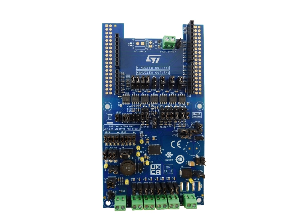
X-NUCLEO-OUT17A1是面向STM32 Nucleo的工业级数字输出扩展板。可提供强大而灵活的评估环境,适用于评估IPS8200HQ-1八路高侧智能电源固态继电器在连接1.0 A工业负载的数字输出模块中的驱动和诊断能力。
X-NUCLEO-OUT17A1通过STISO620和STISO621以及Arduino® UNO R3连接器与STM32 Nucleo上的微控制器相连。
用户可以选择两种驱动模式来控制IPS8200HQ-1:并行模式(当JP21 = 断开时,SEL2 = L)或SPI模式(当JP21 = 闭合时,SEL2 = H)
在SPI模式下,用户还可以选择通信协议:8位模式(当JP22 = 断开时,SEL1 = L)或16位模式(当JP22 = 闭合时,SEL1 = H)
IPS8200HQ-1的VCC电源引脚由连接器CN1提供,而负载(由IPS8200HQ-1的8个输出通道驱动)可连接在CN2、CN3、CN4、CN12与CN1的引脚2之间。
板载数字隔离器(STISO620和STISO621)在两个应用端之间提供2.8k VRMS (4k VPK) 电气隔离:逻辑端与过程端。
逻辑端是MCU的应用端,由VISO_L电源轨供电(3.3 V或5.0 V)。VISO_L可以通过以下方式供电:外部电源(连接到CN13),CN6的引脚4(SW1 = 闭合1-2)或CN6的引脚5(SW1 = 闭合2-3)
过程侧是工业负载的应用端,由VCC和VISO_P电源轨供电。VISO_P(3.3 V或5.0 V)通常由IPS8200HQ-1内置的降压转换器生成的VREG电源轨(JP31 = 闭合)供电(SW17 = 闭合1-2, JP20 = 闭合, JP15 = 闭合且JP28 = 闭合2-4 (VREG = 3.3 V) 或JP28 = 1-3 (VREG = 5.0 V))
也可通过外部电源(连接到CN14)提供VREG(SW17 = 闭合2-3,JP20 = 断开,JP15 = 断开)。
在并行驱动模式下(默认跳线和开关设置下激活),即使没有Nucleo开发板,应用板也可以工作:在这种情况下,用户需通过CN1提供过程端电压(通常为24 V),通过CN13提供VISO_L电压(通常为3.3 V)。INX信号(可通过CN5[1, 2, 3]、CN8[4]和CN9[3, 5, 7, 8]获取)用于控制过程端负载上对应OUTX的开/关状态。
INX引脚的电平可在0 V和VISO_L之间高低切换。每个OUTX (OUT1… OUT8) 的激活状态可通过绿色LED DOX (DO1… DO8) 监测。
三个诊断引脚(TWARN、PGOOD、FAULT)的激活状态可通过红色LED(分别为D11、D12、D13)显示,或通过示波器在CN8[5]、CN5[9]、CN5[10]上监测。
SPI驱动模式可通过更改默认配置激活:(JP21 = 闭合;SW4、SW5、SW6、SW7、SW9、SW10、SW11、SW12、SW13、SW14、SW15、SW20 = 闭合2-3,SW18 = 闭合1-2)。默认SPI模式为8位(JP22 = 断开),16位模式可通过JP22 = 闭合激活。
在SPI驱动模式下,还可通过设置SW3 = 闭合2-3激活MCU冻结检测功能。
该扩展板可以连接到NUCLEO-F401RE或NUCLEO-G431RB开发板。在这种情况下,配套固件X-CUBE-IPS通过读取CN8[1]和CN8[6]上的SEL2_L和SEL1信号,自动检测所选配置(GPIO、SPI-8位、SPI-16位)。MCU冻结功能的激活则由CN9[4]上的WDEN(in)信号检测。
此外,还可以评估一个由X-NUCLEO-OUT17A1与其他扩展板堆叠组成的系统。实际上,SPI驱动模式支持通过Arduino 连接器与另一块堆叠的X-NUCLEO-OUT17A1实现菊花链通信:两块堆叠的开发板需要分别进行以下配置:一块开发板的SW6,SW18 = 闭合2-3,另一块开发板的SW6,SW18 = 闭合1-2。
-
所有功能
- 基于IPS8200HQ-1八路高侧开关,具体特性如下:
工作电压范围:10.5 V至36 V 工作输出电流:≤ 1.0 A 低功耗 (R 欠压锁定 可选择并行或5 MHz SPI(8或16位)驱动模式 嵌入式降压转换器 4x2 LED矩阵可有效显示状态 MCU冻结检测 感性负载的快速衰减 过载和过温保护 接地失效保护 结点过温和奇偶校验诊断引脚 (FAULT) 外壳过温诊断引脚 (TWARN) 电源电压电平诊断引脚 (PGOOD) 采用QFN48L 8x6 mm封装 - 应用板的工作电压范围:12 V至33 V
- 扩展工作电压范围(J9断开)可达36 V
- 工作电流:各通道最高可达1.0 A
- 蓝色LED指示SPI模式选择
- 黄色LED指示SPI 16位模式选择
- 红色LED指示FAULT诊断引脚(JP12闭合)
- 红色LED指示PGOOD诊断引脚(JP13闭合)
- 红色LED指示TWARN诊断引脚(JP27闭合)
- 由STISO620和STISO621确保4 kVPK电气隔离
- 电源轨反向极性保护
- 与STM32 Nucleo开发板兼容
- 配有Arduino® UNO R3连接器
- 通过CE认证
- 符合RoHS和中国RoHS标准
- 基于IPS8200HQ-1八路高侧开关,具体特性如下:
您可能还会喜欢...
特别推荐
所有资源
| 资源标题 | 版本 | 更新时间 |
|---|
MCSDK Board Description (1)
| 资源标题 | 版本 | 更新时间 | ||
|---|---|---|---|---|
| ZIP | 1.0 | 08 Nov 2023 | 08 Nov 2023 |
物料清单 (1)
| 资源标题 | 版本 | 更新时间 | ||
|---|---|---|---|---|
| 1.0 | 08 Nov 2023 | 08 Nov 2023 |
Schematic Pack (1)
| 资源标题 | 版本 | 更新时间 | ||
|---|---|---|---|---|
| 1.0 | 08 Nov 2023 | 08 Nov 2023 |
质量与可靠性
| 产品型号 | Marketing Status | 包 | 等级规格 | 符合RoHS级别 | WEEE Compliant | 材料声明** |
|---|---|---|---|---|---|---|
| X-NUCLEO-OUT17A1 | 批量生产 | CARD | 工业 | Ecopack2 | Yes | |
X-NUCLEO-OUT17A1
Package:
CARDMaterial Declaration**:
(**) st.com上提供的材料声明表单可能是基于包装系列中最常用的封装的通用文档。因此,它们可能不是100%适用于特定的设备。有关特定设备的信息,请联系 销售支持。
样片和购买

| 产品型号 | 供货状态 | Budgetary Price (US$)*/Qty | 从ST订购 | Order from distributors | 包 | 包装类型 | RoHS | Country of Origin | ECCN (US) | ECCN (EU) | 供应商 | 核心产品 | |
|---|---|---|---|---|---|---|---|---|---|---|---|---|---|
| X-NUCLEO-OUT17A1 | | | distributors 无法联系到经销商,请联系我们的销售办事处 |
|
|

X-NUCLEO-OUT17A1 批量生产


